Overview of Silicon-Carbon Anode Material
Our Silicon-Carbon Anode Material is manufactured via an innovative "porous carbon skeleton + vapor-phase silicon deposition + dual carbon coating" process. Nano-silicon particles are uniformly deposited into a porous carbon matrix, forming a composite with a graded buffer structure. This material combines the high lithium storage capacity of silicon with the excellent conductivity and structural stability of carbon.
It is ideal for premium consumer electronics, EV power batteries, energy storage systems, and particularly excels in large-format cylindrical cells, ultra-fast-charging batteries, and solid-state/semi-solid-state batteries.

Silicon-Carbon Anode Material CVD Method for Li-ion Batteries
Featuresof Silicon-Carbon Anode Material
High Specific Capacity: Achieves 3–5 times the capacity of conventional graphite anodes, enabling cell-level energy density exceeding 300 Wh/kg.
Excellent Cycle Stability: The porous carbon skeleton effectively buffers silicon volume expansion, delivering a cycle life of over 3000 cycles.
Superior Rate Performance: The unique conductive network ensures outstanding fast-charge/fast-discharge capability, suitable for 4C and above ultra-fast-charging battery systems.
Batch-to-Batch Consistency: Automated CVD production ensures excellent reproducibility and strict quality control.
Microstructure Design:
Porous Carbon Matrix: Derived from renewable biomass (e.g., coconut shells) via steam activation, providing abundant micropores for silicon deposition and expansion buffering.
Nano-Silicon Particles: < 5 nm in size, deposited via CVD to minimize absolute volume expansion and enhance reaction kinetics.
Gradient Carbon Coating: A uniform coating layer on each composite particle improves electrical conductivity and suppresses side reactions with the electrolyte.
Technical Specifications of Silicon-Carbon Anode Material
Model 2000
|
Item |
Parameter |
Unit |
Standard |
Typical Value |
Test Method / Instrument |
|---|---|---|---|---|---|
|
Particle Size |
Dmin |
μm |
≥ 1.0 |
1.42 |
BT-9300S Laser Diffraction |
|
|
D10 |
μm |
4.0 ± 1.0 |
4.27 |
|
|
|
D50 |
μm |
11.0 ± 1.0 |
11.39 |
|
|
|
D90 |
μm |
21.0 ± 1.0 |
20.49 |
|
|
|
Dmax |
μm |
≤ 36 |
35.65 |
|
|
Tap Density (TAP) |
|
g/cc |
0.6 ± 0.1 |
0.62 |
BT-300 Automatic Tap Tester |
|
Specific Surface Area (SSA) |
|
m²/g |
17 ± 2 |
16.68 |
N₂ Adsorption BET Method |
|
True Density |
|
g/cc |
— |
— |
— |
|
Capacity (1.5V) |
|
mAh/g |
2000 ± 100 |
2018 |
CR2025 (0.8C/0.8C) |
|
1st Efficiency (1.5V) |
|
% |
≥ 89.2% |
89.46 |
|
|
Capacity (0.8V) |
|
mAh/g |
1700 ± 50 |
1687 |
CR2025 (0.8C/0.8C) |
|
1st Efficiency (0.8V) |
|
% |
≥ 86% |
86.25 |
|
|
Trace Elements |
Fe |
ppm |
≤ 20 |
9.42 |
ICP Dissolution Method |
|
|
Co |
ppm |
≤ 5 |
— |
|
|
|
Cu |
ppm |
≤ 5 |
— |
|
|
|
Ni |
ppm |
≤ 5 |
— |
|
|
|
Al |
ppm |
≤ 5 |
— |
|
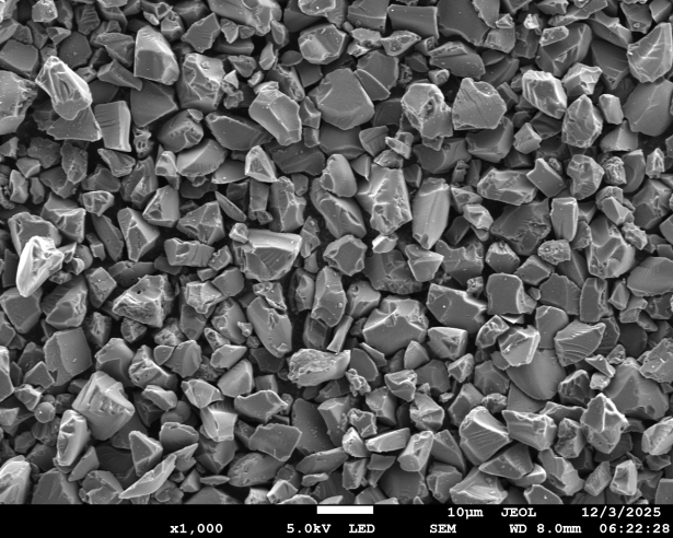
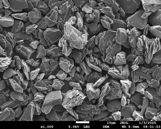
Model 2000 Particle morphology
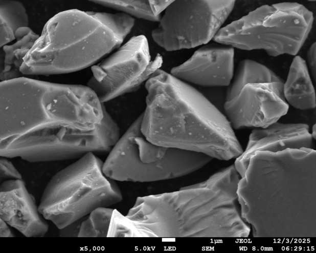
Model 2000 Particle morphology
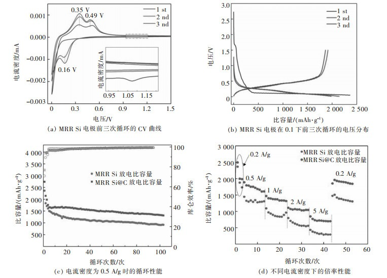
Charge-discharge curve
Model 800
|
Item |
Parameter |
Unit |
Standard |
Typical Value |
Test Method / Instrument |
|---|---|---|---|---|---|
|
Particle Size |
Dmin |
μm |
≥ 1.0 |
1.55 |
BT-9300S Laser Diffraction |
|
|
D10 |
μm |
5.0 ± 1.0 |
5.15 |
|
|
|
D50 |
μm |
12.0 ± 1.0 |
12.11 |
|
|
|
D90 |
μm |
22.0 ± 1.0 |
21.83 |
|
|
|
Dmax |
μm |
≤ 39 |
38.72 |
|
|
Tap Density (TAP) |
|
g/cc |
1.1 ± 0.1 |
1.12 |
BT-300 Automatic Tap Tester |
|
Specific Surface Area (SSA) |
|
m²/g |
≤ 4.5 |
4.1 |
N₂ Adsorption BET Method |
|
True Density |
|
g/cc |
— |
— |
— |
|
Capacity (1.5V) |
|
mAh/g |
800 ± 50 |
810 |
CR2025 (0.8C/0.8C) |
|
1st Efficiency (1.5V) |
|
% |
≥ 90% |
90.65 |
|
|
Capacity (0.8V) |
|
mAh/g |
680 ± 50 |
715 |
CR2025 (0.8C/0.8C) |
|
1st Efficiency (0.8V) |
|
% |
≥ 86% |
87.9 |
|
|
Trace Elements |
Fe |
ppm |
≤ 20 |
— |
ICP Dissolution Method |
|
|
Co |
ppm |
≤ 5 |
— |
|
|
|
Cu |
ppm |
≤ 5 |
— |
|
|
|
Ni |
ppm |
≤ 5 |
— |
|
|
|
Al |
ppm |
≤ 5 |
2.2 |
|
Model 800 Particle morphology
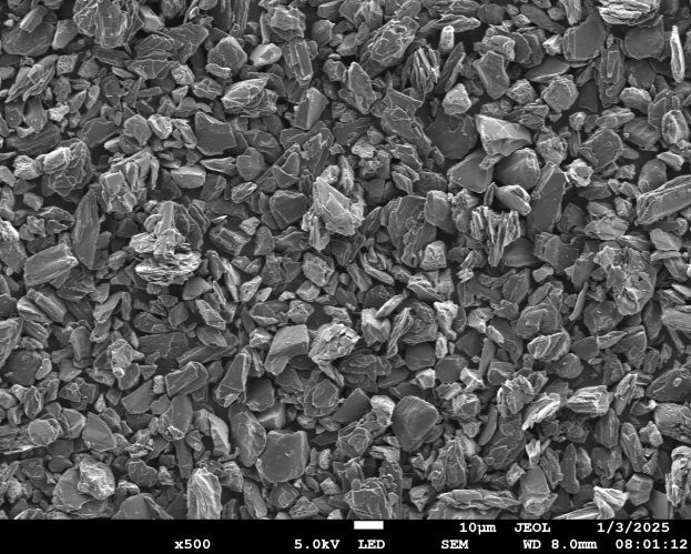
Model 800 Particle morphology
Charge-discharge curve
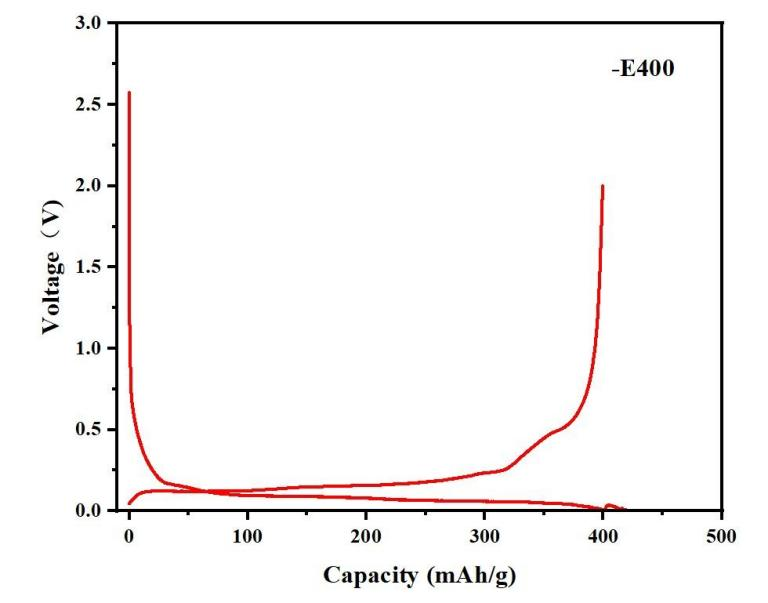
Charge-discharge curve
Applications of Silicon-Carbon Anode Material
EV Power Batteries: When blended with graphite, this material significantly improves energy density and charge rate. It is especially well-suited for large-format cylindrical cells, where the rigid casing effectively constrains silicon expansion, ensuring stability and long cycle life.
Premium Consumer Electronics: Used in smartphones, laptops, wearables, and other 3C devices. It enhances energy density while maintaining fast-charging performance, and has been widely adopted in flagship consumer electronics batteries.
Solid-State / Semi-Solid-State Batteries: This material shows excellent compatibility with sulfide-based solid-state electrolytes. It effectively suppresses silicon expansion and promotes ion transport, making it a core candidate anode material for next-generation solid-state batteries.
Energy Storage Systems: When optimized with graphite blending, it meets the long-cycle-life requirements of grid-scale and commercial & industrial (C&I) energy storage applications.
Package & Handling of Silicon-Carbon Anode Material
Storage: The material is hygroscopic. Once opened, it should be used as soon as possible in a dry environment (dew point ≤ -40°C). Unused portions must be sealed and stored properly.
Handling: To prevent metal contamination during slurry preparation, ceramic or polymer mixing vessels and blades are recommended. Avoid contact with moisture and metal impurities.
FAQs of Silicon-Carbon Anode Material
1. What is the difference between Model 2000 and Model 800?
Model 2000 offers a higher specific capacity (~2000 mAh/g) for maximum energy density, while Model 800 provides a more balanced performance with higher first-cycle efficiency (≥90%) and better cycle stability, making it suitable for applications prioritizing longevity.
2. What is the expected cycle life of this material?
When properly formulated and blended with graphite, our silicon-carbon anode can achieve over 3000 cycles under standard operating conditions, thanks to the porous carbon skeleton that effectively buffers volume expansion.
3. Can this material support ultra-fast charging?
Yes. The unique conductive network structure ensures excellent rate performance, supporting 4C and above fast-charging capabilities, making it ideal for ultra-fast-charge battery systems.
4. How should this material be stored and handled?
The material is hygroscopic. It should be stored in a dry environment (dew point ≤ -40°C) and used promptly after opening. For slurry mixing, use ceramic or polymer equipment to avoid metallic contamination.
5. Is this material compatible with solid-state electrolytes?
Yes. Our material shows excellent compatibility with sulfide-based solid-state electrolytes, effectively suppressing silicon expansion and facilitating ion transport, making it a leading anode candidate for solid-state battery development.